We all have heard the famous slogan, "SAVE WATER". But did we have ever taken some worthful steps to save water? The Answer is NO!!!. But we may contribute in some other ways too.
We usually do waste water by filling the domestic water tank more than its usual capacity,so the water goes uselessly by overflowing. In order to overcome this overflow of water,we are going to build a Alarm circuit to warn us from tank being overflown. So that we can avoid the wastage of water. And this is low budget circuit and can be easily built in our homes :)
Let me tell you the required components for making Water Tank Overflow Alarm circuit:
Now let me explain each components in detail,
STEP DOWN TRANSFORMER:
Step down transformers are used to reduce the voltage according to the required voltage of the circuit.Most of the circuit needs 5V to 12V only. Here i have used 12V transformer to get 12V as output by giving 220/230/240 V as input. One can also use 9V output transformer also.

BRIDGE RECTIFIER:
The output from the transformer is in AC,but we need the supply for circuit in DC. So we need to rectify the AC output to DC output. so the diodes are used to build a Bridge rectifier circuit to convert the 12VAC to 12VDC. A smoothing capacitor can be used at the output side of the rectifier to get a constant vvoltage.

VOLTAGE REGULATOR 7805:
The output DC voltage now available is 12V but it has to be converted into 5V since the transistor base voltage should be in the range of 5V-6V. The working of 7805 is explained in the previous post.
We usually do waste water by filling the domestic water tank more than its usual capacity,so the water goes uselessly by overflowing. In order to overcome this overflow of water,we are going to build a Alarm circuit to warn us from tank being overflown. So that we can avoid the wastage of water. And this is low budget circuit and can be easily built in our homes :)
Let me tell you the required components for making Water Tank Overflow Alarm circuit:
- Step down Transformer(220V/240V to 12V)
- Diodes(for making Rectifier circuit)
- Voltage Regulator 7805
- Transistor bc547
- Relay
- Buzzer
- General purpose Board
- Soldering kit.
Now let me explain each components in detail,
STEP DOWN TRANSFORMER:
Step down transformers are used to reduce the voltage according to the required voltage of the circuit.Most of the circuit needs 5V to 12V only. Here i have used 12V transformer to get 12V as output by giving 220/230/240 V as input. One can also use 9V output transformer also.
BRIDGE RECTIFIER:
The output from the transformer is in AC,but we need the supply for circuit in DC. So we need to rectify the AC output to DC output. so the diodes are used to build a Bridge rectifier circuit to convert the 12VAC to 12VDC. A smoothing capacitor can be used at the output side of the rectifier to get a constant vvoltage.
VOLTAGE REGULATOR 7805:
The output DC voltage now available is 12V but it has to be converted into 5V since the transistor base voltage should be in the range of 5V-6V. The working of 7805 is explained in the previous post.
Voltage regulators are used in the circuits to provide a constant required voltage and to avoid major fluctuations in the voltage to the circuit.
 It has 3 pins. The input pin,ground pin and the output pin. The input voltage must be within the range of 5V to 30V. So the voltage regulator regulates the voltage to 5V.
The circuit now looks like,


The circuit now looks like,
So the regulated voltage is now used to any electronic circuits.
So this output voltage terminal is now immersed inside the watertank.
TRANSISTOR BC547:
BC547 Transistor has Three terminals,
- base
- emitter
- collector
The Emitter is now connected to the ground of the circuit. The Collecter is now connected to the relay. where as whenever the tank level increases and touches the top level terminal(i.e. base terminal)then the transistor starts flowing the current from collector side to the emitter side,so the relay is now activated.
RELAY:
Relay is a Electro-mechanical device. Single pole relay is used in this circuit. The working of this relay is already posted in the blog.It has a common pole where the 220/230/240 V is supplied. when the relay gets activated then NO pole gets the output. The Relay is activated by transistor.(i.e.,when base and 5V from 7805 is shorted,then the transistor conducts current from collector to emitter so the relay is now activated).
BUZZER:
Buzzer is used as alarm. I have used a 230V buzzer here. The neutral is connected directly to the buzzer.but the phase is connected to the NO of the relay.so that when the relay is activated,then the buzzer is in closed circuit and thus alarms.One can also use a 5V buzzer(low voltage)
so that the relay can be avoided in the circuit.
230V buzzer
GENERAL PURPOSE BOARD:
The general purpose board is used to place the whole circuit in a single board and solder.
SOLDERING KIT:
The soldering is used to make a solid connections of the circuit in the general purpose board. Proper precautions and adult supervision is required while soldering.
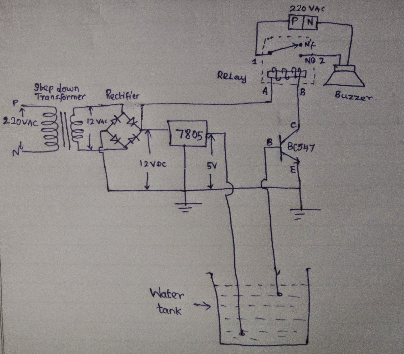
So that's all about the components and connections.Now the whole circuit looks like,
And the above circuit after the soldering work looks like,
So now let us have a look at the working of the Water Tank Overflow Alarm circuit,
Yes!!! It is that easy to build a Water tank Overflow Alarm Circuit. And now we have saved that priceless Water being wasted.
For more :
Subscribe to our Youtube channel:
Simpler Electronics Youtube channel
Become a Fan of our Facebook Page:
https://www.facebook.com/simplerelectronics
Thank you Guys! :) Keep supporting for more projects...


