4/03/2017

Motion Detector using PIR Sensor :: Home Security

             We are very busy/lazy most of the time, due to which there is a chance of the burglar to sneak into your compound(House). In order to identify the suspicious activities like robbing/stealing things in the absence of us in that place, you can implement this simple circuit in our house which can be easily done with basic embedded knowledge.

Simple Description:
             This circuit finds any motion/movement and signals us using the buzzer and LED.

Components Used:

  • Transformer(12V output)
  • Bridge Rectifier 
  • SPDT Switch
  • Battery 9V
  • 7805 Voltage regulator IC
  • 1K ohm Resistor -2
  • LED(RED-1,Yellow-1)
  • BC547 Transistor
  • 5V input Relay
  • PIR Sensor
  • Buzzer
  • Wires
  • General Purpose Board
Most of the components are already discussed in the earlier post of Basic Water Tank Overflow Alarm Circuit Components

So let me explain the left out components with simple description below:

PIR Sensor:

PIR - Passive Infra Red 

It is an electronic sensor that measures infrared (IR) light radiating from objects in its field of view.
This sensor detects any infra red radiations which is emitted by animals, humans, etc.

PIR Sensor

PIR Sensor fixed at Entrance of the house or any place which has to be under surveillance


For more details refer Wikipedia :Wiki : PIR Sensor

SPDT Switch:

Single pole Double throw switch has 2 inputs but a single output.


The above switch  is PCB friendly which can be soldered along the PCB.

The middle terminal is taken as output. While the rest of the terminals are taken as inputs(1.Battery Source,2. 12V DC from Bridge Rectifier)

So the circuit is powered either with the battery source or the stepped down source using the SPDT switch.
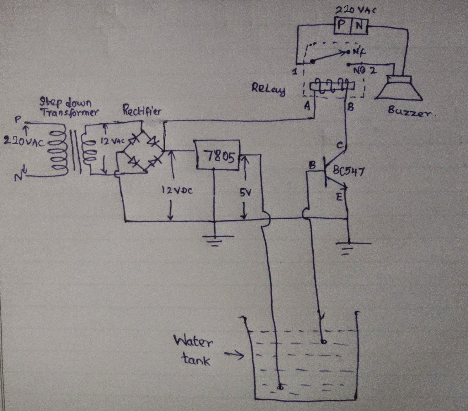

Circuit Diagram:

Use the below schematic for Soldering the  connections among the components.


Now the circuit after soldering the components looks like,

Motion Detector Circuit after soldering the components

The circuit which is been setup inside the House.


Video :

This Video just shows the working scenario of the Circuit.


So Now we are able to find any movement around the surveillance area(PIR sensor fixed area). Now the house/things are secured :)


8/05/2015

Speed Sensors- fascination


There was a fast paced class on Speed sensors two days before. The class gave me an unknown interest for writing this blog today... Though the topic was limited, I was fascinated to produce whatever i got...
                                                                  

                                                              SPEED – a buzz word in today’s scenario, is a measure of fastness. Everybody is in a race and wants to run at the fastest speed without tumbling down. ‘Speed’ is used in variety of contexts and is measured using variety of methods in their own contexts.
According to physics, speed is related to motion. Distance traveled by a moving body in a given time is called speed. Other related terms are angular speed, velocity, and angular velocity. Angular speed is the angular distance per unit time. (Linear) Velocity and angular velocity are vector quantities and are defined as displacement (linear/angular) per unit time.
Measurement of speed is of great significance in variety of application involving some form of motion. While moving in a car/ train or flying in an aircraft or sailing in a ship, we are often interested to know how fast we are moving. In engine control systems, it is imperative to know the speed of moving gears (camshaft/ crankshaft). Scientists involved in missile/rocket systems need to know the velocity at various stages of the flight. Similarly, there are many applications where  measurement of speed is of interest.
Speed is measured using different kinds of sensors operating on different principles.
SENSING PRINCIPLES
Various kinds of principles are employed in speed sensors. Some of them are listed below
1.   Variable reluctance based
2.   Hall effect based
3.   Eddy Current based
4.   Radar Doppler based
5.   LIDAR based
6.   Accelerometer based
7.   Pitot tube based.
8.   Pitometer based.


Let's just make on the first two principles...


1. VARIABLE RELUCTANCE SPEED SENSORS

Variable Reluctance (VR) sensors convert mechanical motion to electric energy without direct contact when positioned near a gear, shaft, rotor, or other regularly moving device. The output signal can be fed electronic circuit. The sensor provides a uncomplicated, accurate, reliable, inexpensive transducer for highly sophisticated control systems.
Variable Reluctance sensor consists of a coil of wire wound around a cylindrical magnetic material, typically a ferrous material and is referred to as a pole piece.  A magnet is attached behind the pole piece, creating a magnetic field through the pole piece and winding. This magnetic field projects out from the pole piece front, also known as the sensor tip.


As the ferromagnetic material, e.g., gear teeth, flywheel or other target features, pass by the sensor tip, the magnetic field is disrupted. The amount of magnetic flux passing through the magnet, and consequently the coil, to varies. Due to the time varying flux, a voltage is induced in the coil.
When the target feature is moved close to the sensor, i.e. the air gap between the sensor and the target is reduced, the flux increases. When the target is moved further away, the flux reduces. Thus, the motion of the target feature results in a time-varying flux that induces a proportional voltage in the coil. The amplitude and frequency of the induced voltage is proportional to the speed of the target feature.
This voltage signal is fed to the electronic circuitry that processes it to output the signal in the desired format.
Typical applications of these sensors are the measurement of speed of Gear tooth (in Crankshaft, Camshaft) and sensing the turbine speed of a jet engine.

Advantages
       Variable reluctance sensors are passive sensors as they don’t require external power supply
      As the wire and magnets used are pretty inexpensive, these sensors are low cost sensors
      They are light weight, robust and can work in harsh(high temperature and high vibration) environments

Disadvantages
      Target material must be ferrous only.
      As the magnitude of the induced voltage in these sensors is proportional to target speed, it becomes difficult to design circuitry appropriate for very low speed signals. Thus Variable Reluctance sensors have a definite lower limit on the speed of the target.
      Though sensors themselves are cheap, the cost advantage is offset by the additional electronic circuitry required to process the low amplitude induced voltages.


2. HALL EFFECT SPEED SENSORS
                                                    Hall Effect speed sensor uses a Hall Effect transducer element between the magnet and the target. As in VR sensors, the induced flux due to movement of the target is detected. But a Hall transducer is sensitive only to the magnitude of flux; it does not sense its rate of change.
Hall Effect speed sensors overcome the limitation of VR sensors of lower speed limit. Hall Effect speed sensors can detect targets moving at arbitrarily slow speeds, or even the presence or absence of non-moving targets. It supports zero speed sensing.
The target material can be either ferrous or magnetic.


Advantages
      Signal processing electronics is often integrated into the same package as the transducer. Most Hall Effect speed sensors directly provide a digital output signal that is directly compatible with digital logic, micro controllers, and PLC’s
      This reduces the amount of pickup from interference sources, and makes Hall Effect speed sensors highly immune to Electromagnetic Interference induced malfunctions and failures. Operating temperatures are high. 


7/19/2015

Electronic Car Parker

INTRODUCTION:


                             Automatic light/dark activated systems have very common utilities in day to day life. For example, street lighting at night, morning alarm, automatic emergency light, dark activated buzzers and so on. The project explained here can be used in several such systems. This circuit has a sensor component which works in response to the ambient light condition. The output of this sensor is compared with a set reference value and whenever the light condition changes from dark to light or light to dark, the output goes high.

In this project, the surrounding illumination is observed by a LDR which acts as a sensor for the circuit. The voltage drop across this LDR corresponds to a particular intensity of light. This value can be taken at the inverting input of a comparator of LM339 or LM324 (at pin6). The resistor R3 (1kthis input. The non-inverting input (pin7) is connected to a variable resistor (preset) which is used to set the reference voltage of the comparator.


EXPLANATION:


A comparator works on the principle that its output remains high as long as the non-inverting input is at higher level than that at its inverting input. Here, the output (pin1) is connected to an LED. This concept can be utilized in two configurations (night activation and day activation, respectively) by changing the positions of R3 and LDR as shown the circuit diagrams. The reference voltage is set to correspond to a light intensity between day and night. A preset VR1 (100k whose range varies on adjustment).

In the first case, the LED will glow when LDR is completely dark, i.e., very less light falls on it. In such a condition, the resistance of LDR is higher than that offered by the preset. This causes a lower potential at pin6 than that at pin7 and so the output goes high thus lighting the LED. The second case is exact opposite to this. This time pin6 goes lower than pin7 when the LDR receives bright light. This activates the LED in the next circuit. Thus considering which LED is ON, we can easily get guided to park our car.

A simulated circuit is shown for easy learning.


REQUIRED COMPONENTS

1.LDR


2.LED


3.LM339 OR LM324 (Comparators)


4.POTS(100K)


5.RESISTORS(1K, 10K)


We focus on simplicity with no compromise in output. For effective output use IR sensors(Infrared sensors).

Good Luck... :) 


11/15/2014

How to make WaterTank Overflow Alarm Circuit?

We all have heard the famous slogan, "SAVE WATER". But did we have ever taken some worthful steps to save water? The Answer is NO!!!. But we may contribute in some other ways too.
We usually do waste water by filling the domestic water tank more than its usual capacity,so the water goes uselessly by overflowing. In order to overcome this overflow of water,we are going to build a Alarm circuit to warn us from tank being overflown. So that we can avoid the wastage of water. And this is low budget circuit and can be easily built in our homes :)

Let me tell you the required components for making Water Tank Overflow Alarm circuit:

  • Step down Transformer(220V/240V to 12V)
  • Diodes(for making Rectifier circuit)
  • Voltage Regulator 7805
  • Transistor bc547
  • Relay
  • Buzzer
  • General purpose Board
  • Soldering kit.

Now let me explain each components in detail,

STEP DOWN TRANSFORMER:
Step down transformers are used to reduce the voltage according to the required voltage of the circuit.Most of the circuit needs 5V to 12V only. Here i have used 12V transformer to get 12V as output by giving 220/230/240 V as input. One can also use 9V output transformer also.


BRIDGE RECTIFIER:
The output from the transformer is in AC,but we need the supply for circuit in DC. So we need to rectify the AC output to DC output. so the diodes are used to build a Bridge rectifier circuit to convert the 12VAC to 12VDC. A smoothing capacitor can be used at the output side of the rectifier to get a constant vvoltage.


VOLTAGE REGULATOR 7805:
The output DC voltage now available is 12V but it has to be converted into 5V since the transistor base voltage should be in the range of 5V-6V. The working of 7805 is explained in the previous post.
Voltage regulators are used in the circuits to provide a constant required voltage and to avoid major fluctuations in the voltage to the circuit.

It has 3 pins. The input pin,ground pin and the output pin. The input voltage must be within the range of 5V to 30V. So the voltage regulator regulates the voltage to 5V.
The circuit now looks like,

So the regulated voltage is now used to any electronic circuits.
So this output voltage terminal is now immersed inside the watertank.


TRANSISTOR BC547:
BC547 Transistor has Three terminals,
  • base
  • emitter
  • collector
Here the base terminal is connected to a long wire which is kept at the top level of the water tank.
The Emitter is now connected to the ground of the circuit. The Collecter is now connected to the relay. where as whenever the tank level increases and touches the top level terminal(i.e. base terminal)then the transistor starts flowing the current from collector side to the emitter side,so the relay is now activated.


RELAY:
Relay is a Electro-mechanical device. Single pole relay is used in this circuit. The working of this relay is already posted in the blog.It has a common pole where the 220/230/240 V is supplied. when the relay gets activated then NO pole gets the output. The Relay is activated by transistor.(i.e.,when base and 5V from 7805 is shorted,then the transistor conducts current from collector to emitter so the relay is now activated).

BUZZER:
Buzzer is used as alarm. I have used a 230V buzzer here. The neutral is connected directly to the buzzer.but the phase is connected to the NO of the relay.so that when the relay is activated,then the buzzer is in closed circuit and thus alarms.One can also use a 5V buzzer(low voltage)
so that the relay can be avoided in the circuit. 
230V buzzer

GENERAL PURPOSE BOARD:
The general purpose board is used to place the whole circuit in a single board and solder.


SOLDERING KIT:
The soldering is used to make a solid connections of the circuit in the general purpose board. Proper precautions and adult supervision is required while soldering.


So that's all about the components and connections.Now the whole circuit looks like,

And the above circuit after the soldering work looks like,


So now let us have a look at the working of the Water Tank Overflow Alarm circuit,


Yes!!! It is that easy to build a Water tank Overflow Alarm Circuit. And now we have saved that priceless Water being wasted.

For more :
Subscribe to our Youtube channel:
Simpler Electronics Youtube channel

Become a Fan of our Facebook Page:
https://www.facebook.com/simplerelectronics

Thank you Guys! :) Keep supporting for more projects...

11/12/2014

Voltage Regulators 78XX

Voltage regulators are used in the circuits to provide a constant required voltage and to avoid major fluctuations in the voltage to the circuit.

The most common voltage regulators used are
1.7805
2.7809
3.7812

7805 voltage regulator:
It has 3 pins. The input pin,ground pin and the output pin. The input voltage must be within the range of 5V to 30V. So the volage regulator regulates the voltage to 5V.
The connections are shown as;

So the regulated voltage is now used to any electronic circuits,
i.e. Light sensor,dark sensor circuits,etc,.

Voltage Regulator 7905:

The differences in 7905 from 7805 is that the output voltage is negative and the pins are changed.

The picture shows the differences between the 78XX and 79XX regulators

some other voltage regulators ,which has different output voltages are

7812: output voltage is 12V

7809: output voltage is 9V


So that's the basic informations of the most widely used voltage regulators.


11/11/2014

Simple Practical representation of a Relay.


Single pole relay:

The relay has 5 terminals,
1.Normally open(NO) contact
2.Normally closed(NC) contact
3.common contact
4.Terminal A of the coil
5.Terminal B of the coil

Practical Representation:


The Terminals A and B of the coil are excited by a 5V battery. so the coil gets excited and thus attracts the pole ,so the pole moves from NC to NO contact . Now the supply given to the common terminal starts flowing through the NO contact. so the load connected to that terminal starts working.

Lets Start Learning and make Electronics more Simpler...